
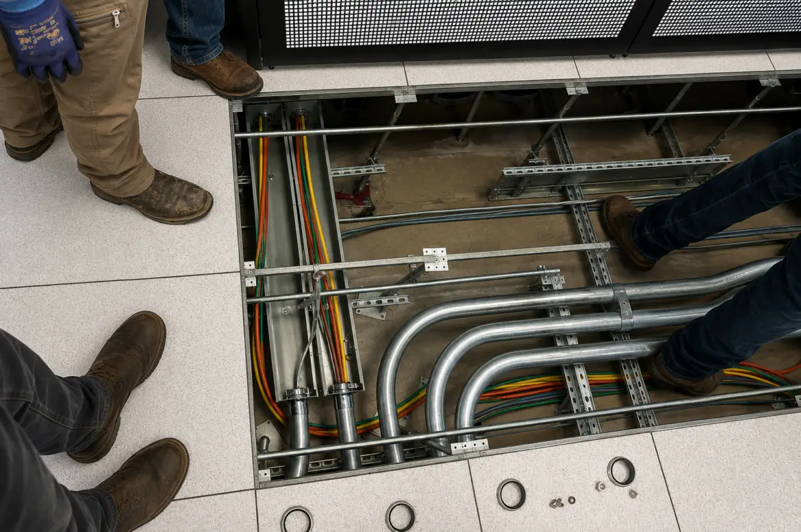
Electrical safety depends on more than installing a breaker and pulling conductors between two points. The conductor must be correctly sized for the load and installation conditions, while the grounding and bonding system must provide a dependable path for fault current.
These decisions affect whether equipment operates properly, whether overcurrent protection clears a fault, and whether exposed metal can become an electrical hazard.
For contractors, a careful material takeoff and a few additional field checks can prevent overheating, nuisance trips, failed inspections, equipment damage, and dangerous touch voltage.
1. Do Not Size Conductors by Breaker Rating Alone
A common starting point is the circuit’s overcurrent protection, but conductor sizing involves more than matching a familiar wire size to a breaker.
Before selecting a conductor, consider:
- Calculated load
- Continuous and noncontinuous loads
- Conductor material
- Insulation type
- Terminal temperature ratings
- Ambient temperature
- Number of current-carrying conductors
- Raceway fill
- Installation environment
- Distance and voltage drop
- Equipment instructions
- Applicable electrical code
The National Electrical Code is the principal benchmark for electrical design and installation in residential, commercial, and industrial occupancies. Contractors should use the code edition adopted by the local jurisdiction, along with project specifications and manufacturer instructions.
A conductor that appears large enough based only on breaker size may require adjustment because of heat, bundling, terminal limitations, or the characteristics of the connected load.
2. Confirm Copper or Aluminum Before Ordering
Copper and aluminum conductors have different properties and are not automatically interchangeable at the same size.
Before installing either material, verify:
- The conductor size required for that material
- Whether the equipment terminals are rated for copper, aluminum, or both
- The permitted conductor type and stranding
- The connector’s conductor range
- Preparation requirements
- Required tightening torque
- Whether joint compound is required by the manufacturer
- Whether the connector is suitable for the environment
A lug marked CU is intended for copper. A lug marked AL is intended for aluminum. A dual-rated lug will typically be marked for both, but the installer must still confirm the permitted conductor sizes and installation instructions.
Never assume that a connector is dual rated because an aluminum conductor physically fits inside it.
3. Account for Terminal Temperature Ratings
Conductor insulation may have a temperature rating higher than the connected equipment terminal. That does not automatically permit the conductor’s full high-temperature ampacity to be used.
The allowable ampacity calculation must account for the temperature limitations of the equipment and terminations.
This becomes especially important when working with:
- Larger feeders
- Panelboards
- Disconnects
- Transformers
- Service equipment
- Motor equipment
- Aluminum conductors
- Equipment with mixed terminal ratings
The conductor, connector, terminal, and equipment must function as a complete listed system.
4. Check for Derating Before the Wire Is Pulled
Heat cannot escape as easily when many current-carrying conductors share a raceway or cable assembly. High ambient temperatures can further reduce a conductor’s allowable ampacity.
Conditions that deserve additional review include:
- Multiple circuits in one conduit
- Conductors installed above hot equipment
- Rooftop raceways
- Boiler and mechanical rooms
- Industrial process areas
- Long bundled cable runs
- Outdoor installations exposed to direct sunlight
- Spaces with limited ventilation
These conditions are easiest to address during estimating and layout. Discovering after the conductors are installed that a larger size or additional raceway was needed can create an expensive correction.
5. Consider Voltage Drop on Long Runs
A conductor can meet basic ampacity requirements and still produce poor equipment performance if the run is long enough to create excessive voltage drop.
Possible symptoms include:
- Dim lighting
- Slow motor acceleration
- Motor overheating
- Contactors dropping out
- Reduced equipment performance
- Nuisance control problems
- Poor operation during startup
- Customer complaints at distant receptacles
Long branch circuits and feeders may justify increasing the conductor size even when the smaller conductor satisfies the minimum ampacity requirement.
Voltage-drop review is particularly useful for:
- Detached buildings
- Parking lot lighting
- Site lighting
- Pumps
- HVAC equipment
- Motors
- Sign circuits
- Agricultural buildings
- Outdoor receptacles
- Equipment with high starting current
Increasing conductor size may also require larger raceway, fittings, terminals, and grounding hardware, so the entire material list should be reviewed together.
6. Grounding and Bonding Are Not the Same
The terms are often used together, but they perform different functions.
Grounding connects an electrical system to earth.
Bonding connects conductive components together to create electrical continuity and an effective path for fault current.
Article 250 of the NEC addresses grounding and bonding requirements. NFPA emphasizes that grounding and bonding are distinct concepts, even though both are essential to the electrical safety system.
The earth itself should not be treated as the normal low-impedance path intended to clear a branch-circuit or feeder fault. The bonding and equipment-grounding system provides the metallic path that allows sufficient fault current to return to the source and operate the breaker or fuse.
7. Bond Every Required Metal Component
Metal equipment that may become energized must be connected into the equipment-grounding and bonding system as required for the installation.
Examples can include:
- Panelboard cabinets
- Disconnect enclosures
- Junction boxes
- Pull boxes
- Metal raceways
- Cable tray
- Transformers
- Motor frames
- Generator enclosures
- Service equipment
- Certain concentric or eccentric knockouts
- Separately derived systems
Loose fittings, missing bonding jumpers, painted surfaces, improper locknuts, and unsuitable connectors can interrupt the intended fault-current path.
UL provides specific guidance on bonding around concentric and eccentric knockouts, particularly for installations over 250 volts.
The fact that two metal parts touch does not necessarily mean the connection provides an acceptable bonding path.
8. Keep Neutrals and Equipment Grounds in Their Proper Roles
The grounded conductor—commonly called the neutral—normally carries return current from the load.
The equipment-grounding conductor is intended to carry current during a fault condition.
Improperly bonding neutrals and equipment grounds downstream of the permitted bonding point can place normal return current on metal raceways, enclosures, equipment frames, water piping, and other conductive paths.
Contractors should pay particular attention when working with:
- Subpanels
- Detached structures
- Generators
- Transfer switches
- Transformers
- Separately derived systems
- Existing services that have been altered
- Older installations with questionable bonding
Do not install bonding screws or straps simply because they were included with the equipment. Their use depends on where the equipment is installed and how the system is configured.
9. Use Listed Grounding and Bonding Products
Grounding and bonding products are not generic pieces of hardware. The connector must be listed and identified for its application, conductor material, conductor range, and environment.
UL 467 is the safety standard covering grounding and bonding equipment.
Products commonly used in grounding and bonding work include:
Ground Rods
Ground rods are used as grounding electrodes where required or permitted. The rod material, diameter, length, installation method, and connections must be appropriate for the project and applicable requirements.
Ground Rod Clamps
Use a clamp listed for the conductor, electrode, and installation environment.
A clamp used below grade or in direct contact with earth must be identified for that use. A general-purpose clamp should not be substituted simply because it fits around the rod.
Lay-In Ground Lugs
Lay-in lugs allow a conductor to be installed without feeding the entire conductor through a closed connector.
They are useful on:
- Enclosures
- Cable tray
- Equipment frames
- Ground bars
- Industrial equipment
- Telecommunications installations
For example, ILSCO offers dual-rated aluminum lay-in grounding lugs in different conductor ranges, including products for both solid and stranded conductors.
Always verify the lug’s conductor range, material rating, mounting method, hardware, and environmental suitability.
Split-Bolt Connectors
Split bolts are commonly used for certain copper conductor taps, splices, and grounding connections.
Selection must be based on:
- Conductor material
- Main and tap conductor sizes
- Solid or stranded construction
- Listing
- Environmental conditions
- Insulation requirements
- Manufacturer instructions
Different split bolts cover different conductor ranges. Using an oversized connector on a small conductor, or forcing a conductor into an undersized connector, can produce an unreliable connection.
Compression Connectors
Compression lugs and taps can provide durable connections when installed using the specified connector, die, tool, and number of compressions.
Do not assume that any crimper capable of deforming the barrel creates a listed connection. The complete connector and tooling system must be compatible.
Bonding Bushings and Bonding Locknuts
These fittings may be required where ordinary locknuts do not provide the necessary bonding connection.
Applications can include:
- Service raceways
- Certain concentric or eccentric knockouts
- Higher-voltage systems
- Installations requiring bonding around impaired connections
- Raceways containing grounding electrode conductors
- Equipment specified by the engineer or inspector
A bonding bushing must also be connected with a correctly sized bonding jumper and suitable lug.
Ground Bars and Ground Bar Kits
Ground bars provide organized termination points for equipment-grounding and bonding conductors.
Use the correct bar and mounting kit for the enclosure. Some applications require the bar to be bonded directly to the enclosure, while neutral bars in downstream equipment may need to remain isolated.
Bonding Jumpers
Bonding jumpers maintain electrical continuity around components or between conductive parts.
They may be made from:
- Copper conductor
- Aluminum conductor where permitted
- Braided bonding straps
- Listed flexible bonding jumpers
- Equipment-specific bonding components
The conductor size, connector type, routing, and protection from physical damage all matter.
10. Prepare Conductors and Contact Surfaces Properly
A connector can only perform as intended when the conductor and mounting surface are prepared correctly.
Before making a connection:
- Verify the conductor is clean and undamaged
- Strip the correct length
- Avoid nicking conductor strands
- Remove only the insulation required
- Follow instructions for oxide removal
- Use joint compound when specified
- Confirm the connector accepts the conductor material
- Ensure mounting surfaces permit the required electrical contact
- Use listed hardware
- Protect the completed connection from moisture and corrosion
Paint, rust, dirt, oxidation, loose hardware, and damaged strands can compromise a grounding or bonding connection.
Do not remove coatings or modify listed equipment unless permitted by the equipment instructions.
11. Torque Connections to the Manufacturer’s Specification
“Good and tight” is not a measurable installation standard.
An undertightened connection can loosen, overheat, or develop resistance. An overtightened connection can damage the conductor, strip threads, crack the connector, or deform the terminal.
Contractors should use an appropriate calibrated torque tool where a torque value is specified.
Before energizing equipment:
- Confirm the required torque
- Use the correct tool
- Tighten each connection to specification
- Follow any sequencing instructions
- Apply required torque markings
- Record values when project documentation requires it
- Recheck connections only when instructed by the manufacturer
This applies to phase conductors, neutrals, grounding conductors, bonding jumpers, lugs, breakers, disconnects, transformers, and equipment terminals.
12. Size Connectors for the Actual Conductor
A larger lug is not always more versatile.
Every connector has an approved conductor range. A conductor below that range may not be held securely, while a conductor above the range may be damaged or may not fully enter the connector.
Before ordering a connector, confirm:
- Minimum conductor size
- Maximum conductor size
- Copper, aluminum, or dual rating
- Solid or stranded conductor
- Number of conductors permitted
- Wire class or stranding limitations
- Required mounting hardware
- Environmental rating
- Direct-burial approval where applicable
Never place multiple conductors under one terminal unless that terminal is specifically identified for the number and type of conductors being used.
13. Inspect the Entire Fault-Current Path
Grounding and bonding should be evaluated as a continuous system rather than a collection of isolated parts.
Trace the intended fault-current path through:
- The equipment enclosure or frame
- The equipment-grounding conductor or approved metal raceway
- Junction and pull boxes
- Feeder equipment
- The service or separately derived system bonding point
- The grounded source conductor
- The transformer or utility source
A missing locknut, loose lug, broken conductor, unbonded box, or improper neutral connection anywhere along this path can prevent the protective device from operating as intended.
14. Pay Special Attention to Renovations
Existing installations often contain conditions that are not obvious until equipment is opened.
Contractors may encounter:
- Neutral and ground conductors mixed downstream
- Missing equipment-grounding conductors
- Metal boxes with no bonding connection
- Improper grounding clips
- Corroded clamps
- Undersized conductors
- Aluminum conductors landed on unsuitable terminals
- Multiple conductors under single-rated lugs
- Abandoned grounding electrode conductors
- Flexible raceway without required bonding provisions
- Water-pipe connections that have been interrupted by plastic repairs
Document questionable conditions before extending or modifying the system. New equipment does not correct an unsafe grounding or bonding path elsewhere in the installation.
A Better Material Checklist
Before leaving the supply house, verify that the job has more than the correct footage of wire.
Depending on the project, the complete material list may include:
- Copper or aluminum building wire
- Bare or insulated equipment-grounding conductor
- Grounding electrode conductor
- Ground rods
- Listed ground rod clamps
- Lay-in lugs
- Mechanical lugs
- Compression lugs and taps
- Correct compression dies
- Split-bolt connectors
- Ground bars
- Bonding bushings
- Bonding locknuts
- Bonding jumpers
- Braided grounding straps
- Suitable mounting hardware
- Joint compound when specified
- Insulating and sealing materials
- Weatherproof or direct-burial connectors
- Conductor identification
- Torque tools and torque marking materials
Ordering compatible products together reduces return trips and helps prevent field substitutions that may not be suitable for the installation.
Safety Starts Before the Wire Is Pulled
Proper wire sizing, grounding, and bonding begin during estimating and material selection—not after the equipment is installed.
A reliable installation requires the contractor to consider the load, conductor, insulation, terminals, raceway, connectors, environmental conditions, overcurrent protection, and complete fault-current path as one coordinated system.
Taking time to verify these details protects the customer, the equipment, the contractor, and everyone who may work on the system later.
Wire and Grounding Products from CAPO Supply
CAPO Supply provides electrical contractors with products for residential, commercial, and industrial wiring installations, including:
- Copper and aluminum building wire
- Equipment-grounding conductors
- Ground rods and clamps
- Grounding and bonding lugs
- Split-bolt connectors
- Mechanical and compression connectors
- Ground bars
- Bonding bushings and locknuts
- Bonding jumpers
- Raceway and fittings
- Enclosures and panel accessories
Our team can help identify compatible conductor, connector, fitting, and grounding products based on the job requirements and manufacturer specifications.
Contact CAPO Supply before your next project to make sure the entire installation—from conductor sizing to the final bonding connection—is covered.
This article provides general educational information and is not a substitute for an engineered design, job-specific calculations, manufacturer instructions, the locally adopted electrical code, or requirements established by the authority having jurisdiction. Electrical work should be performed by qualified professionals.